
I’m going to try my hand at building some QRP gear. I purchased a few items from the 4 States QRP Group, and a 20 meter transceiver from “QRP-Labs” to start my QRP setup.
The first item is the “Bayou Jumper” 
It is a single band, 5 watt CW transceiver. The kit is enclosed in a wooden box and includes 2 40 meter CW crystals.
From the 4 states qrp group page:
Return with us now to those thrilling days of yesteryear” and build the Bayou Jumper. The name “Bayou Jumper” is a play on “Ocean Hopper”, a famous regenerative receiver of a bygone era. It retains that great retro look but with modernized circuitry. With it’s distinctive panel and wood box enclosure it pays homage to the famous spy radios of WWII. It is designed for the CW segment of the 40 meters.
I picked up a couple extra 40 meter crystals and a crystal holder to add to the project. The enclosure is a wooden box, available from Hobby Lobby. There are 3, different sized boxes in the set, the smaller one being used for the Bayou Jumper. I also picked up the larger one to hold a battery pack, the antenna tuner (for random wire antennas) and a few other odds and ends. For the kit enclosure, I am going to put my qrp cw clubs numbers and frequencies on the inside of the lid, kind of a handy reference guide. I have yet to figure out what I want to put on the outside of the box. Something like my call and the radio name is all I have so far, now just to figure out how I am going to make it permanent and unique.

Here are the 2 circuit boards. The bottom board is the “face plate” of the radio. This is the before modification picture, there are 2 holes that need to be drilled, one on either side of the circle labeled “tuning”. These holes are for the add-on kit, the “Soup’er Up’er” which adds a filter and a fine tuning adjustment. The locations for these holes are marked on the back side of the board.
Here is the face of the radio with the Soup’er Up’er modifications

Next, we have the components.

The upper right is the BNC jack, to the left of that is the DC plug and jack. The DC plug will be terminated with Anderson Powerpoles, more on that later. The 2 jacks in the next row are for the headphones and external key or keyer Interface (the radio has a built in key). The rest of the components are the knobs for various controls.

Here are the Capacitors, semiconductors and diodes.

These are the resistors, trimmer caps and crystal mounting hardware. Note, the grey plastic holder in the lower right did not come with the kit. I purchased this separately, along with a couple different crystals. That long silver bar towards the top of the photo, that’s the built in key “arm”.

Here is some wire for winding the torroid. In the center of the picture are the 2 crystals supplied with the kit. The small bag at the bottom holds the stand offs and screws to mount the circuit board to the face.

The crystal holders and 3-position switch.

The 2 extra crystals.

The box has a stand-off glued into each corner to hold the boards. I will stain and age the box to give it a “vintage” look.
The first thing to do is to prepare the face plate to accept the switch and fine tune adjustment pot. The locations to drill these holes are plated onto the back side of the face plate circuit board. It’s easiest to get this out of the way first, as the first few components are placed on the main board and checked for fit to the face. I can check the positioning of the “new” components at this time too.
Construction is pretty straight forward, if you follow the instructions. Make sure you inventory the parts and group the same value components together before you start. I skipped this step and paid for it during the installation of the capacitors. I had an extra 0.0033 uF ceramic monolithic capacitor, and missing a 0.001 uF. The size, shape and color are the same for the 2 components. The markings are very hard to read as the coating is shiny and the markings are shiny. I ended up going back and double checking all the components I had already soldered on the board to make sure I didn’t accidentally mix up the values. The components were correct, I guess I lucked out. An email was sent to the person who packaged the kit to see if I could get a replacement component. A few days later, the part arrived in the mail. While I was waiting, I got the holes drilled for the crystal holder, and am ready to complete the project.
QRP-Labs Gear
The first kit I assembled from QRP-Labs was the 20W dummy load. The kit consists of 2 circuit boards, 22 (2 extra) 1K resistors, a 1N4004 diode, a 10 nF capacitor and a BNC connector.
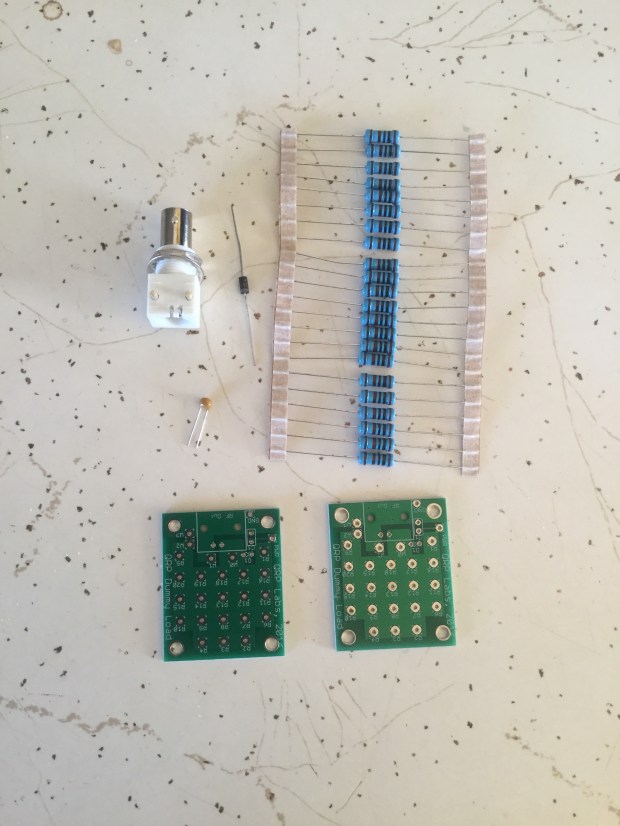
The dummy load consists of 20, 1K ohm 1W resistors connected in parallel to make a 50-ohm 20W QRP dummy load. The diode and capacitor are used as a simple RF detector that rectifies and smooths the peak voltage. It can be read by DVM as a simple indication of output power, but it is not accurate. The finished dummy load is below.


